Introduction
Have you ever thought of robots that are involved in sports and recreation activities? Robots that could mimic the act of athletes like runners and, gymnasts. Such robots are extremely interesting for robotics enthusiasts, makers, and inventors. One of the sports and recreation activities that attract boys and girls, young and adults are ziplining.
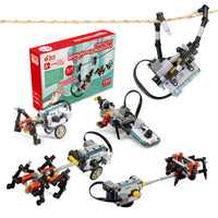
Ziplines are designed to transfer cargo or a person from the top to the bottom of the inclined cable. The cargo or the person is propelled by gravity and moves on the cable through a freely rotating pulley. The zipline robot that we are going to make looks like a monkey that moves on a cable by using its two arms. Making such a creature that uses its arms for locomotion on a cable is a challenging task. However, in this tutorial, we are going to make a fun and easy-to-build zipline robot with LEGO®-compatible components, an Arduino board, and some off-the-shelf electromechanical components (Fig. A). The instructions are prepared in a way that you can build them at home.

As shown in Fig. A zipline robot hangs itself from a cable and uses its two arms for locomotion across the cable. In its simplest setup, the zipline robot is made of LEGO®-compatible components, an off-the-shelf DC gear motor, 3D printed parts, and an ON/OFF toggle switch (Fig. B).

For more sophisticated applications, an Arduino NANO board is added to the zipline robot to significantly increase the expandability and programming elements of the project (Fig. C). As you know, various adds-on shields can be added to any Arduino board to expand the project’s capabilities.

For instance, in the current project, a microphone from Adafruit is added to the zipline robot that enables a user to control the motions of the robot by clapping (Fig. D). This feature adds a lot of interactivity to the zipline robot. For example, you can control the speed of the robot by clapping, so that, the faster you clap, the faster it goes. Very fascinating.
In this tutorial, we will make the zipline robot’s body structure out of LEGO®-compatible pieces and then drive the arm’s mechanical mechanism using an off-the-shelf DC gear motor that is attached to the body structure through a 3D-printed housing. The gear motor’s torque is transferred through a pair of bevel and worm gears to both arm mechanisms.
What materials do you need to build a zipline robot?

- 1x 9v Battery Connector
- 1x TT Gear Motor
- 1x 3D Printed Gear Motor Housing
- 1x 3D Printed Lego-compatible Coupling
- 2x Breadboard, Mini Size
- 1x Arduino Nano
- 1x M3 x 10 Machine Screw
- 1x M3 x 30 Machine Screw
- 1x L298N Mini Motor Driver
- 1x MAX4466 Microphone Module
- 1x Power Jack, Barrel Type
- 1x Mini Switch, Toggle Type
- Male to Male Jumper Wire

- Frame, 5x7-module
- Beam, 5-module
- Beam, 3-module
- Double bevel gear, 36-tooth
- Gear, 24-tooth
- Worm gear
- Double cross block, 3-module
- Connector peg with friction/axle, 2-module
- Connector peg with friction, 3-module
- Bevel gear, 12-tooth
- Gear, 8-tooth
- Angular block 2, 180°
- Axle, 2-module
- Bushing/axle extender, 2-module
- Bushing, 1-module
- Angular block, 5(157.5°)
- Connector peg with axle, 2-module
- Connector peg with friction, 2-module
- 1- Axle, 8module| 2- Axle, 7module| 3- Axle, 5module| 4- Axle, 3module
- T-beam, 3x3 module
- Angular block, 6 (90°)
- Axle connector with axle hole
- Angular block 1, 0°
- Connector peg, 2-module
- Axle with ball, 2-module
How to use building blocks to assemble the robot?
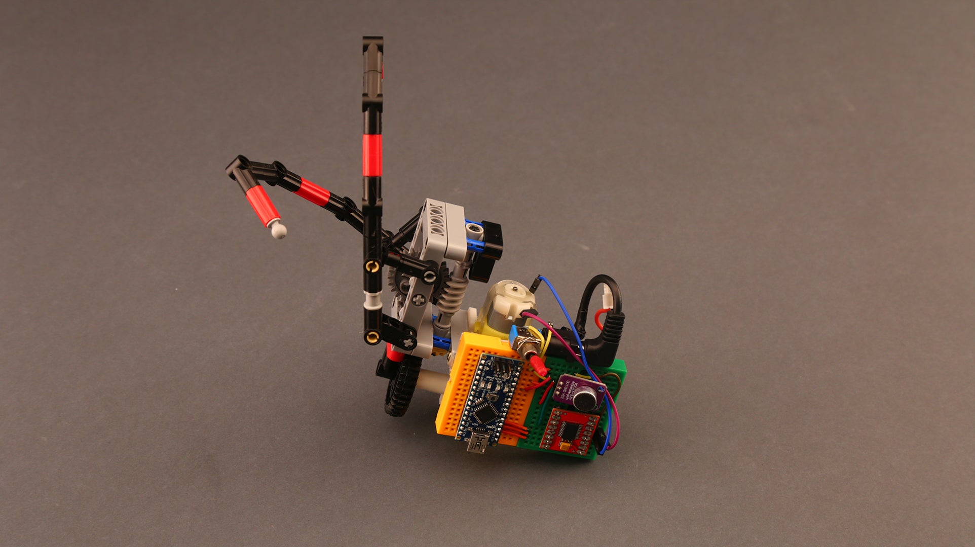
Let's start assembling the zipline body-structure. It is a structure that holds a crank-rocker 4-bar linkage mechanism that creates the required arm’s motions for ziplining (Fig. G). The motor’s torque is transferred to the arm mechanisms through a pair of bevel gears and a worm drive.
Prepare the LEGO®-compatible pieces according to Fig. F, and follow the step-by-step video tutorial below.
What 3D printed parts do you need?
Lego-compatible components only match with Lego-compatible gear motors. In order to transmit power from the shafts of the off-the-shelf gear motors to LEGO®-compatible gears or axles, we need to print a housing for the gear motor as well as a coupling (Fig. H). The housing serves as an interface or an adaptor between the gear motor and the LEGO®-compatible beams. The coupling connects the gear motor shaft with the Lego-compatible axle. These 3D printed parts are called LEGO®-compatible housing and shafts (Fig. I). Please download the 3D files and print the motor housing, LEGO®-compatible coupling with your 3D printer, or use the ones in a maker space nearby.

|

|
Electronics and wiring
Prepare your screwdriver and soldering iron and carefully follow the video instructions below. Make sure you properly implement the schematic circuit diagram shown in Fig. J, so you don't end up toasting your Arduino board and motor driver.

Programming your DIY robot
You can pick up LEGO®-compatible pieces and let your imagination go limitless. Of course, coding is also the part that you can have lots of fun and be the most creative. You can go to Arduino IDE and write your own code to tell the zipline robot what to do. But for now, let's start with this code.
    #define micPin A6
    #define motorPinA 9
    #define motorPinB 10
    #define motorPinPWM 11
    void setup() {
    // Initialize Arduino pins to outputs
    pinMode(motorPinA, OUTPUT);
    pinMode(motorPinB, OUTPUT);
    pinMode(motorPinPWM, OUTPUT);
    }
    unsigned int sample, clapTime = 0;
    void loop() {
    unsigned long samplingBeginning = millis();
    unsigned int loudness = 0;
    unsigned int signalMax = 0;
    unsigned int signalMin = 1024;
    // Sample microphone data
    while (millis() - samplingBeginning < 100) {
    sample = analogRead(micPin);
    // Measure min and max value of the signal
    if (sample > signalMax)
    signalMax = sample;
    else if (sample < signalMin)
    signalMin = sample;
    }
    loudness = signalMax - signalMin;
    // Referesh the clapTime if a clap is detected
    if (peakToPeak > 300)
    clapTime = millis();
    // Run the motor if a clap is detected recently
    if (millis() - clapTime < 200)runTheMotor();
    else stopTheMotor();
    }
    // Motor driver pin configuration to run
    void runTheMotor() {
    digitalWrite(motorPinA, HIGH);
    digitalWrite(motorPinB, LOW);
    analogWrite(motorPinPWM, 255);
    }
    // Motor driver pin configuration to stop
    void stopTheMotor() {
    digitalWrite(motorPinA, HIGH);
    digitalWrite(motorPinB, HIGH);
    analogWrite(motorPinPWM, 0);
    }