Introduction
Nowadays, it is absolutely crucial to provide kids with tools and toys that encourage them to step into programming as part of their STEAM curricula. Tangible coding is a new approach to kid’s coding education. It is easy to start and provides kids with early access to programming. Tangible coding takes advantage of the kid’s non-computer knowledge to express language syntax. It also provides an opportunity for kids to become involved in programming with no screen used. The concept of tangible programming is similar to text-based programming languages in terms of sequential execution of instructions. But, instead of typing the instructions, either physical blocks are placed/stacked together or buttons are pressed whereas each object or button represents a coding instruction such as commands and flow-of-control structures. Children can put building blocks together or press push buttons in different orders to create a program.
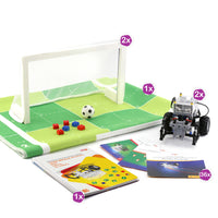
A tangible coding console usually comes with a robot that executes the coding commands generated by the user (Fig. A). In this project, we called a tangible coding robot. Therefore, kids can easily program their robots to perform a different variety of tasks such as moving on a specific path or doing object manipulation. If a marker is attached to the robot, kids can program the robot to move on different paths to generate drawing patterns on a paper sheet. They can also create beautiful scenes by having their robot dance.
In the present project, we have made a robot and a remote tangible coding console out of Lego-compatible, custom-built 3D printed parts, two off-the-shelf DC gear motors, an Arduino board, NRF modules, and five pushbuttons. You can go ahead and program your robot to move on a specific path by pressing the colored push buttons on the coding console (Fig. B).

The coding console and the robot are shown in Fig. B. When a user presses the push buttons on different orders, a program is created and saved in the Arduino board located on the coding console. The coding commands are then sent to the robot using a communication channel established using an NRF module.

In this tutorial, we will make the structure of the body of the robot using LEGO®-compatible parts. Then, two DC gear motors will drive the differential mechanism of the robot to move on any path on the plane (Fig. C).

In the next step, we will add an Arduino Nano board as the brain of the tangible coding robot. Arduino Nano uses a small-size powerful microprocessor that makes it suitable for low-weight and small-size projects (Fig. D).

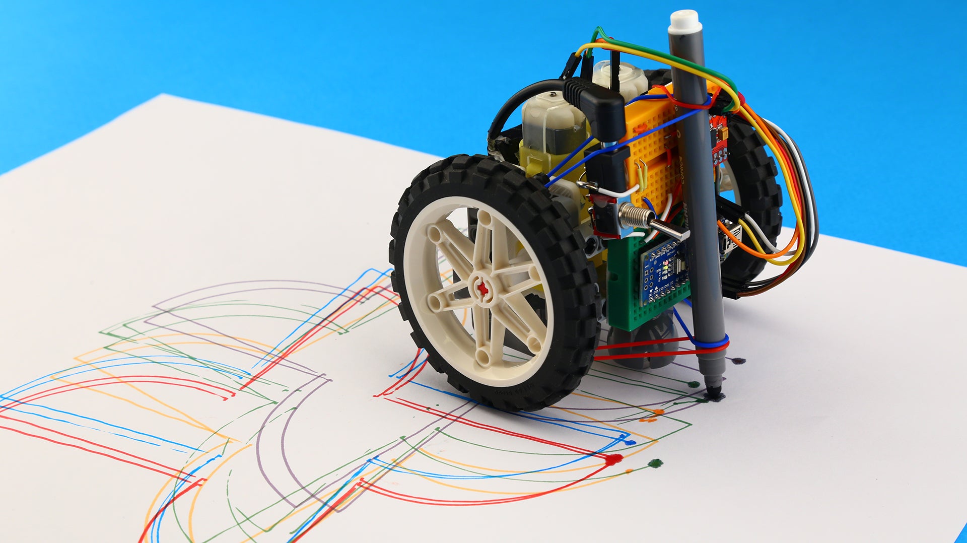
Various off-the-shelf motors, sensors, LEDs can be easily connected to Arduino boards. This feature enables us to do a variety of tasks with this robot. For instance, you can draw patterns on a paper by attaching a marker (Fig. E) or add RGB LEDs to play around with light colors (Fig. F).

The operator console has five push buttons for controlling the robots to go forward (white), backward (green), turn right (red), turn left (blue), and run (yellow) (Fig. G). The command signals are then transmitted to the robot using the NRF module. The instructions are given in a way that you can easily make one at home.

What materials do you need to build a Hexapod robot?

- 2x Breadboard, 83 x 52 x 9mm
- 2x Arduino Nano
- 1x Driver Motor
- 2x NRF 24L01, without Antenna Module
- 1x Buzzer, Active Type
- 1x Breadboard, Mini Size
- 1x Mini Switch, Toggle Type
- 2x Power Jack, Barrel Type
- 1x Pushbutton
- Male to Male Jumper Wire

- TT Gear Motor
- 3D Printed Gear Motor Housing
- Frame, 5x7 module
- Steel ball & ball bearing
- Wheel 61.6mm D. x 13.6mm Motorcycle
- T-Beam, 3x3 module
- Connector peg with friction, 2-module
- 3D Printed Lego-compatible Coupling
- Beam, 9-module
- 2x M3 x 16 Machine Screw
- 1x M3 x 30 Machine Screw
- Double cross block, 3-module
- Axle, 2-module
- Connector peg with friction/axle, 2-module
- Beam, 7-module
- 2x M3 Nut
- 2x M3 Nut
How to use building blocks to assemble the robot?
Let’s start off by assembling the body structure of the robot. The body structure holds everything together including the wheels, the casters, and the electronics. Prepare the LEGO®-compatible pieces according to Fig. I, and follow the step-by-step video tutorial below.
What 3D printed parts do you need?
In order to hold the DC gear motors in place and make a proper connection to the LEGO®-compatible, we have used custom-designed, LEGO®-compatible, 3D printed motor housings and shaft couplings (Fig. J). Download and print out the motor housings, couplings. Then prepare the required Lego-compatible parts from Fig. I, and follow the step-by-step mechanical assembly tutorial.

Electronics and wiring
For this project, you need to assemble both the robot and the coding console circuits (Figs. K, and L). For assembling the electronic circuits of the tangible coding console and the robot, follow the video instructions and the schematics carefully.


Programming your DIY robot
Double-check the warnings from the previous section and make sure everything is assembled exactly according to the circuit diagrams. Now that you have completed the assembly, it’s time to program your robot. Upload the provided codes to your robot and its coding console.
Robot:
#define motorRightA A0
#define motorRightB A1
#define motorRightPWM 6
#define motorLeftA A2
#define motorLeftB A3
#define motorLeftPWM 5

#include <SPI.h>
#include <nRF24L01.h>
#include <RF24.h>
#include <Servo.h>
RF24 radio(9, 10); // CE, CSN

// Setup Adafriut Neopixel LED Ring
#include <Adafruit_NeoPixel.h>
#define PIXELSPIN 4
#define NUMPIXELS 16
Adafruit_NeoPixel pixels = Adafruit_NeoPixel(NUMPIXELS, PIXELSPIN, NEO_GRB + NEO_KHZ800);

const byte address[6] = "00010";
const int motorSpeed = 80, straightTimeDelay = 600, turningTimeDelay = 560;


void setup() {
  radio.begin();
  radio.openReadingPipe(0, address);
  radio.setPALevel(RF24_PA_MIN);
  radio.startListening();
  pixels.begin(); // Adafriut Neopixel begin
  for (int i = 0; i < 17; i++) {
    pixels.setPixelColor(i, pixels.Color(0, 0, 0));
    pixels.show();
  }
}

void loop() {

  if (radio.available()) {
    // Take and decode instructions
    char instructions[50] = "";
    radio.read(&instructions, sizeof(instructions));

    for (int i = 0; i < sizeof(instructions); i++) {
      char message = instructions[i];
      stopTheRobot();
      delay(200);
      if (message == 'f') {
        goForward();
      } else if (message == 'b') {
        goBackward();
      } else if (message == 'r') {
        goRight();
      } else if (message == 'l') {
        goLeft();
      } else if (message == 's') {
        stopTheRobot();
        break;
      }
    }
  }
}

void goForward() {
  digitalWrite(motorRightA, LOW);
  digitalWrite(motorRightB, HIGH);
  analogWrite(motorRightPWM, motorSpeed);
  digitalWrite(motorLeftA, HIGH);
  digitalWrite(motorLeftB, LOW);
  analogWrite(motorLeftPWM, motorSpeed);

  pixels.setPixelColor(6, pixels.Color(200, 200, 190));
  pixels.setPixelColor(7, pixels.Color(200, 200, 190));
  pixels.setPixelColor(8, pixels.Color(200, 200, 190));
  pixels.setPixelColor(9, pixels.Color(200, 200, 190));
  pixels.setPixelColor(10, pixels.Color(200, 200, 190));
  pixels.show();

  delay(straightTimeDelay);
  for (int i = 0; i < 17; i++) {
    pixels.setPixelColor(i, pixels.Color(0, 0, 0));
    pixels.show();
  }
}
void goBackward() {
  digitalWrite(motorRightA, HIGH);
  digitalWrite(motorRightB, LOW);
  analogWrite(motorRightPWM, motorSpeed);
  digitalWrite(motorLeftA, LOW);
  digitalWrite(motorLeftB, HIGH);
  analogWrite(motorLeftPWM, motorSpeed);

  pixels.setPixelColor(0, pixels.Color(0, 200, 0));
  pixels.setPixelColor(1, pixels.Color(0, 200, 0));
  pixels.setPixelColor(2, pixels.Color(0, 200, 0));
  pixels.setPixelColor(14, pixels.Color(0, 200, 0));
  pixels.setPixelColor(15, pixels.Color(0, 200, 0));
  pixels.show();

  delay(straightTimeDelay);
  for (int i = 0; i < 17; i++) {
    pixels.setPixelColor(i, pixels.Color(0, 0, 0));
    pixels.show();
  }
}
void goLeft() {
  digitalWrite(motorRightA, LOW);
  digitalWrite(motorRightB, HIGH);
  analogWrite(motorRightPWM, motorSpeed);
  digitalWrite(motorLeftA, LOW);
  digitalWrite(motorLeftB, HIGH);
  analogWrite(motorLeftPWM, motorSpeed);

  pixels.setPixelColor(2, pixels.Color(0, 0, 210));
  pixels.setPixelColor(3, pixels.Color(0, 0, 210));
  pixels.setPixelColor(4, pixels.Color(0, 0, 210));
  pixels.setPixelColor(5, pixels.Color(0, 0, 210));
  pixels.setPixelColor(6, pixels.Color(0, 0, 210));
  pixels.show();

  delay(straightTimeDelay);
  for (int i = 0; i < 17; i++) {
    pixels.setPixelColor(i, pixels.Color(0, 0, 0));
    pixels.show();
  }
}
void goRight() {
  digitalWrite(motorRightA, HIGH);
  digitalWrite(motorRightB, LOW);
  analogWrite(motorRightPWM, motorSpeed);
  digitalWrite(motorLeftA, HIGH);
  digitalWrite(motorLeftB, LOW);
  analogWrite(motorLeftPWM, motorSpeed);

  pixels.setPixelColor(10, pixels.Color(200, 0, 0));
  pixels.setPixelColor(11, pixels.Color(200, 0, 0));
  pixels.setPixelColor(12, pixels.Color(200, 0, 0));
  pixels.setPixelColor(13, pixels.Color(200, 0, 0));
  pixels.setPixelColor(14, pixels.Color(200, 0, 0));
  pixels.show();

  delay(straightTimeDelay);
  for (int i = 0; i < 17; i++) {
    pixels.setPixelColor(i, pixels.Color(0, 0, 0));
    pixels.show();
  }
}
void stopTheRobot() {
  digitalWrite(motorRightA, HIGH);
  digitalWrite(motorRightB, HIGH);
  analogWrite(motorRightPWM, 0);
  digitalWrite(motorLeftA, HIGH);
  digitalWrite(motorLeftB, HIGH);
  analogWrite(motorLeftPWM, 0);
}
Coding console:
#define forward_button 8
#define backward_button 4
#define right_button 7
#define left_button 5
#define startstop_button 6
#define buzzerPin A0
#define auxGnd A2 //auxiliary ground pin

#include <SPI.h>
#include <nRF24L01.h>
#include <RF24.h>
RF24 radio(9, 10); // CE, CSN

const byte address[6] = "00010";

void setup() {
  radio.begin();
  radio.openWritingPipe(address);
  radio.setPALevel(RF24_PA_MIN);
  radio.stopListening();
  pinMode(auxGnd, OUTPUT);
  pinMode(buzzerPin, OUTPUT);
  digitalWrite(auxGnd, LOW);
}

void loop() {
  //Take the instructions (50 instructions in a row maximum)
  char instructions[50];
  for (int i = 0; i < sizeof(instructions); i++)
    instructions[i] = NULL;

  boolean runTheProgram = false;

  int i = 0;
  while (i < sizeof(instructions)) {
    buzz(100);
    while (true) {
      if (!digitalRead(forward_button)) {
        while (!digitalRead(forward_button));
        instructions[i] = 'f';
        break;
      } else if (!digitalRead(backward_button)) {
        while (!digitalRead(backward_button));
        instructions[i] = 'b';
        break;
      } else if (!digitalRead(left_button)) {
        while (!digitalRead(left_button));
        instructions[i] = 'r';
        break;
      } else if (!digitalRead(right_button)) {
        while (!digitalRead(right_button));
        instructions[i] = 'l';
        break;
      } else if (!digitalRead(startstop_button)) {
        while (!digitalRead(startstop_button));
        runTheProgram = true;
        break;
      }
    }
    i++;
    if (runTheProgram)
      break;
  }
  instructions[i] = 's';
  buzz(800);
  radio.write(&instructions, sizeof(instructions));
}

void buzz(int duration) {
  digitalWrite(buzzerPin, HIGH);
  delay(duration);
  digitalWrite(buzzerPin, LOW);
}
You are all set. Your robot is ready to go.