Introduction
Rescue robots are designed to assist humans in search and rescue operations. They usually assist rescue crews in tasks such as searching, 2D/ 3D mapping of the search area, removing rubbles and object manipulations, delivering supplies, and or evacuating casualties from disastrous sites. For instance, rescue robots were used in the Fukushima nuclear disaster in 2016. As rescue robots work in disastrous sites, they should be able to move on rough trains. Therefore, their locomotion mechanism should enable them to go over the steps and inclined terrains. They are usually equipped with tracked locomotion mechanisms, as it provides high traction for the rescue robots to move on uneven surfaces. They should also be equipped with a robotic manipulator to enable object grasping and manipulation (Fig. A).

Rescue robots that are controlled by an operator from a safe distance are called teleoperated robots (Fig. B). In this case, the operator sends command signals to the robot through a communication channel. The robot follows the commands to safely move toward the target locations and, for example, to manipulate objects or to displace rubbles.

If the size of the rescue robot is small, it can be deployed in confined and tiny places where larger rescue robots cannot operate (Fig. C).

In practice, they’re sent out to find victims or shut off the gas valves in collapsed buildings, or disastrous sites. Hence, they are all equipped with grippers as their primary tool to utilize in the field (Fig. D). The operator’s proficiency in controlling the robot from a distance, agility, and durability of the locomotion mechanism, dexterity of the robotic manipulator or gripper, and the capacity of the communication channel are the main issues affecting the whole rescue operation.

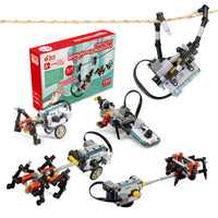
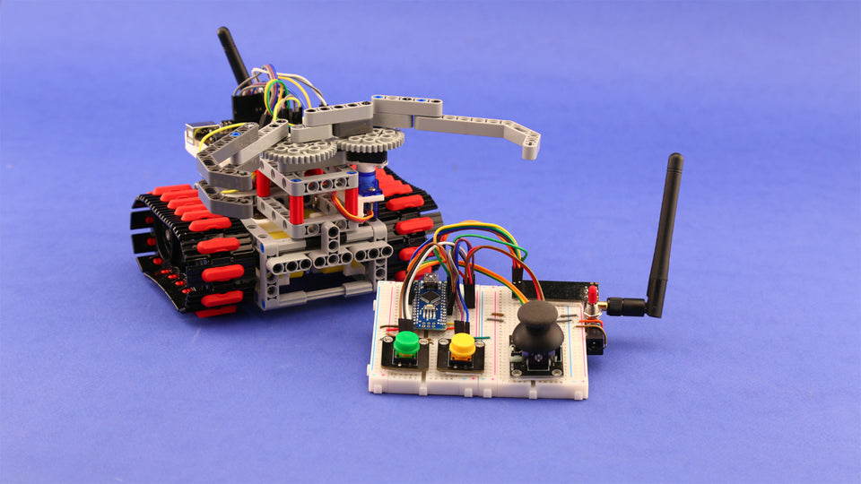
In this tutorial, we will show you how to make a teleoperated rescue robot out of LEGO®-compatible pieces, Arduino boards, off-the-shelf DC and servo motors, NRF communication modules, and joystick module. The current project uses an Arduino Uno and Nano boards as the main controller of the robot and the operator console, respectively (Fig. E).

The body structure of the robot is made of LEGO®-compatible pieces. Arduino boards and DC and servo motors are then connected to LEGO®-compatible pieces using custom-designed 3D printed parts. The servo motor is in charge of opening and closing the gripper, and DC gear-motors are used to provide the main movements of the robot.
The operator console has a joystick for controlling the robot’s main movements and two pushbuttons for the opening and closing of the gripper (Fig. F). The command signals are transmitted to the robot using the NRF module. The instructions are given in a way that you can easily make one at home.

What materials do you need to build a Hexapod robot?

- 1x 3D Printed Arduino Uno Holder
- 1x Servo Motor
- 1x Servo Motor Lego-compatible horn
- 1x Servo Motor Lego-compatible housing
- 2x TT Gear Motor
- 2x 3D Printed Gear Motor Housing
- 1x Joystick Module
- 1x Arduino Uno
- 1x Arduino Nano
- 1x Breadboard, Mini Size
- 2x Breadboard, 83 x 52 x 9mm
- 2x Push Button, Tactile Type
- 1x Driver Motor
- 1x Power Jack, Barrel Type
- 1x Buzzer, Active Type
- 2x 3D Printed Lego-compatible Coupling
- 1x M3 x 30, 2x M3 x 16 Machine Screw
- 2x M2 x 16 Screw
- 4x M3 Flat Washer
- 1x Mini Switch, Toggle Type
- 2x NRF 24L01, Antenna Module
- Male to Male Jumper Wire
- 2x RP-SMA Antenna

- Track, 5x1, 5-module
- Double angular beam, 3x7-module
- Beam, 9-module
- Beam, 7-module
- Beam, 5-module
- Beam, 3-module
- T-Beam, 3x3 module
- Frame, 5x7 module
- Bushing/axle extender, 2-module
- Connector peg with friction, 2-module
- Connector peg with friction, 3-module
- Axle, 2-module
- Bushing, 1-module
- Connector peg with friction/axle, 2-module
- Axle with stop, 4-module
- Axle, 3-module
- Double connector peg, 3-module
- Gear, 40-tooth
- Sprocket, 40, 7x15 mm
How to use building blocks to assemble the robot?
Let’s start off by assembling the body structure of the robot. The body structure holds everything together including the track mechanism, the gripper, and the electronics. Prepare the LEGO®-compatible pieces according to Fig. H, and follow the step-by-step video tutorial below.
After the body structure is completed, it’s time to add the gripper (Fig. I). The gripper consists of a pair of gears that rotate in opposite directions. Each gear holds one jaw of the gripper. Inside the gripper mechanism, a servo motor is in charge of the opening and closing of jaws. For snapping the gears in place, note their initial positioning in the assembly instructions video. If they snap lopsided, your gripper won’t work properly.

What 3D printed parts do you need?
In order to hold Arduino Uno, DC gear motors, and the servo motor in place and make a proper connection to the LEGO®-compatible pieces, we have used custom-designed, LEGO®-compatible 3D printed motor housings, Arduino holder, and shaft couplings (Fig. J, K, and L). Download and print out the Arduino holder, motor housings, couplings, servo motor housing, and servo motor horn. Then get the required LEGO®-compatible parts from Fig. H and follow the step-by-step mechanical assembly tutorial.

|

|

|
Electronics and wiring
For this project, you need to assemble both the robot and operator console circuits (Figs. M, and N). So, let’s break down this section into two parts.
For the robot part, download and print out our LEGO®-compatible Arduino Uno holder so that you can properly place your Arduino on your robot. For the rest of this section and for assembling the remote controller just follow the video instructions and the schematics carefully.


Programming your DIY robot
Double-check the warnings from the previous section and make sure everything is assembled exactly as the circuit diagram. Now that you have completed the assembly, it’s time to program your robot. Upload the provided codes to your robot and its operator console.
Rescue robot:
#define servo 2
#define motor_leftpwm 5
#define motor_rightpwm 6
#define motor_left_d 3
#define motor_left_a 4
#define motor_right_a 9
#define motor_right_d 8
#define buzzer A5
#define aux_gnd_1 A4
#define aux_gnd_2 A3
#define aux_vcc A2

#include <SPI.h>
#include <nRF24L01.h>
#include <RF24.h>
#include <Servo.h>

RF24 radio(10, 7); // CE, CSN
Servo gripper;

const byte address[6] = "00001";
int gripperPos = 90;

void setup() {

  Serial.begin(115200);
  pinMode(servo, OUTPUT);
  pinMode(motor_left_a, OUTPUT);
  pinMode(motor_left_d, OUTPUT);
  pinMode(motor_right_a, OUTPUT);
  pinMode(motor_right_d, OUTPUT);
  pinMode(motor_rightpwm, OUTPUT);
  pinMode(motor_leftpwm, OUTPUT);
  pinMode(buzzer, OUTPUT);
  pinMode(aux_gnd_1, OUTPUT);
  pinMode(aux_gnd_2, OUTPUT);
  pinMode(aux_vcc, OUTPUT);

  digitalWrite(motor_left_a, HIGH);
  digitalWrite(motor_left_d, HIGH);
  digitalWrite(motor_right_a, HIGH);
  digitalWrite(motor_right_d, HIGH);
  digitalWrite(aux_gnd_1, LOW);
  digitalWrite(aux_gnd_2, LOW);
  digitalWrite(aux_vcc, HIGH);
  gripper.attach(servo);
  gripper.write(90);
  radio.begin();
  radio.openReadingPipe(0, address);
  radio.setPALevel(RF24_PA_MIN);
  radio.startListening();
}

void loop() {
  if (radio.available()) {
    char message[32] = "";
    radio.read(&message, sizeof(message));
    if (message[0] == '1')closeGripper();
    else if (message[1] == '1')openGripper();
    if (message[2] == '1')digitalWrite(buzzer, HIGH);
    else digitalWrite(buzzer, LOW);
    driveRobot(message[3], message[4], message[5], message[6]);
  }
}

// Gripper
void closeGripper() {
  gripperPos++;
  gripper.write(gripperPos);
  delay(10);
}

void openGripper() {
  gripperPos--;
  gripper.write(gripperPos);
  delay(10);
}

//Driverobot
void driveRobot(char X_dir, char Y_dir, char X, char Y) {
  int X_val, Y_val;
  if (X == '4')X_val = 240;
  else if (X == '3')X_val = 180;
  else if (X == '2')X_val = 120;
  else if (X == '1')X_val = 60;
  else if (X == '0')X_val = 0;
  if (Y == '4')Y_val = 240;
  else if (Y == '3')Y_val = 180;
  else if (Y == '2')Y_val = 120;
  else if (Y == '1')Y_val = 60;
  else if (Y == '0')Y_val = 0;
  if (X_dir == '1')X_val *= -1;
  if (Y_dir == '1')Y_val *= -1;

  float r = 0.75 * sqrt(pow(X_val, 2) + pow(Y_val, 2));
  float theta = atan2(Y_val, X_val);
  if (theta < 0)theta += 2 * PI;
  float rightMotorVal, leftMotorVal;
  float slope = 4 / PI;
  if (theta <= PI / 2) {
    leftMotorVal = 1;
    rightMotorVal = -1 + slope * theta;
  } else if (theta <= PI) {
    leftMotorVal = 1 - slope * (theta - PI / 2);
    rightMotorVal = 1;
  } else if (theta <= 3 * PI / 2) {
    leftMotorVal = -1;
    rightMotorVal = 1 - slope * (theta - PI);
  } else if (theta <= 2 * PI) {
    leftMotorVal = -1 + slope * (theta - 3 * PI / 2);
    rightMotorVal = -1;
  }

  leftMotorVal *= r;
  rightMotorVal *= r;

//Motors
  int rightMotorDir = rightMotorVal < 0 ? 1 : 0;
  int leftMotorDir = leftMotorVal < 0 ? 1 : 0;
  rightMotorVal = floor(abs(rightMotorVal));
  leftMotorVal = floor(abs(leftMotorVal));

  if (rightMotorDir) {
    digitalWrite(motor_right_a, HIGH);
    digitalWrite(motor_right_d, LOW);
    analogWrite(motor_rightpwm, rightMotorVal);
  } else {
    digitalWrite(motor_right_a, LOW);
    digitalWrite(motor_right_d, HIGH);
    analogWrite(motor_rightpwm, rightMotorVal);
  }

  if (leftMotorDir) {
    digitalWrite(motor_left_a, LOW);
    digitalWrite(motor_left_d, HIGH);
    analogWrite(motor_leftpwm, leftMotorVal);
  } else {
    digitalWrite(motor_left_a, HIGH);
    digitalWrite(motor_left_d, LOW);
    analogWrite(motor_leftpwm, leftMotorVal);
  }
}
Operator console:
#define js_click A0
#define js_y A1
#define js_x A2
#define yellow_button 5
#define green_button 4
#include <SPI.h>
#include <nRF24L01.h>
#include <RF24.h>

RF24 radio(9, 10); // CE, CSN
const byte address[6] = "00001";
int jsY_offset, jsX_offset;

void setup() {
  Serial.begin(115200);
  pinMode(js_click, INPUT_PULLUP);
  pinMode(js_y, INPUT_PULLUP);
  pinMode(js_y, INPUT_PULLUP);
  pinMode(yellow_button, INPUT_PULLUP);
  pinMode(green_button, INPUT_PULLUP);
  radio.begin();
  radio.openWritingPipe(address);
  radio.setPALevel(RF24_PA_MIN);
  radio.stopListening();
  jsY_offset = analogRead(js_y);
  jsX_offset = analogRead(js_x);
}

void loop() {
  int jsX = jsY_offset - analogRead(js_y);
  int jsY = jsX_offset - analogRead(js_x);
  int jsC = digitalRead(js_click);
  int yellowButton = !digitalRead(yellow_button);
  int greenButton = !digitalRead(green_button);
  char yellowButton_char = yellowButton == 0 ? '0' : '1';
  char greenButton_char = greenButton == 0 ? '0' : '1';
  char jsY_dir = jsY > 0 ? '0' : '1';
  char jsX_dir = jsX > 0 ? '0' : '1';
  char jsC_char = jsC == 0 ? '1' : '0';
  char jsY_abs, jsX_abs;
  if (abs(jsY) > 400)jsY_abs = '4';
  else if (abs(jsY) > 300)jsY_abs = '3';
  else if (abs(jsY) > 200)jsY_abs = '2';
  else if (abs(jsY) > 100)jsY_abs = '1';
  else if (abs(jsY) > 0)jsY_abs = '0';
  if (abs(jsX) > 400)jsX_abs = '4';
  else if (abs(jsX) > 300)jsX_abs = '3';
  else if (abs(jsX) > 200)jsX_abs = '2';
  else if (abs(jsX) > 100)jsX_abs = '1';
  else if (abs(jsX) > 0)jsX_abs = '0';

  const char message[] = {yellowButton_char, greenButton_char,
                          jsC_char, jsX_dir, jsY_dir, jsX_abs, jsY_abs
                         };
  radio.write(&message, sizeof(message));
}
You are all set. Your robot is ready to go.